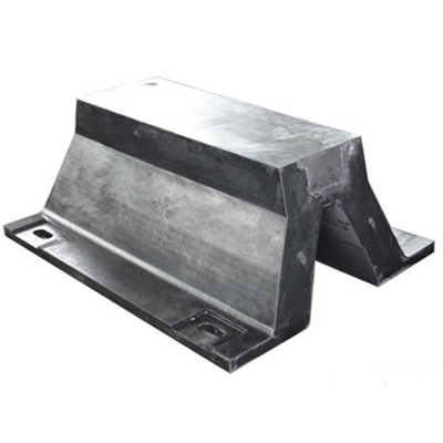
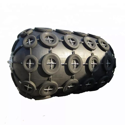
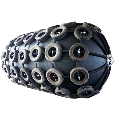
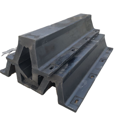
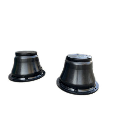
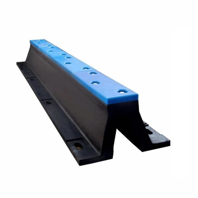
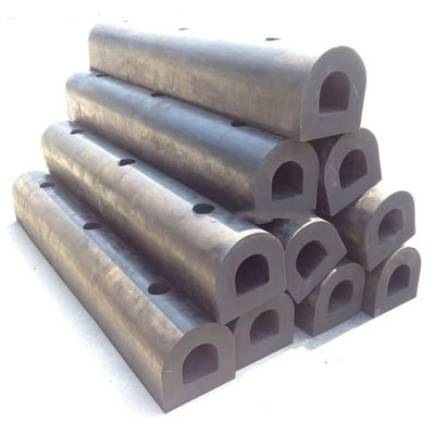
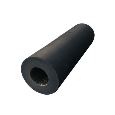
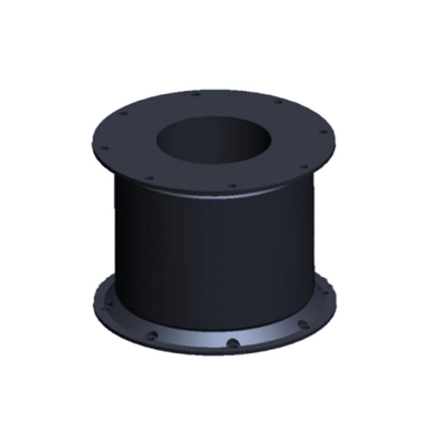
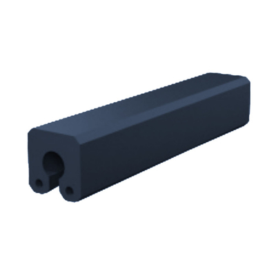
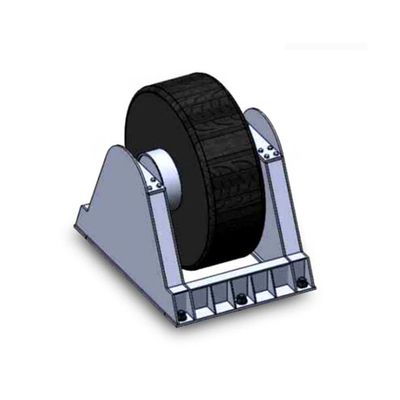
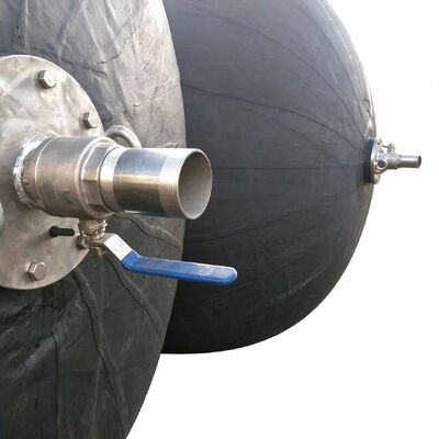
Ballasted Pneumatic Submarine Rubber Fenders — Customized Size for Navy Dock
Submarine fenders are specialized marine protection systems designed to reduce contact loads between submarine hulls and berth structures during berthing, departure, repositioning, and maintenance operations. Unlike conventional fenders used for general commercial vessels, submarine fender systems must be selected with particular attention to hull geometry, contact location, underwater operating conditions, berth configuration, and the operational requirements of the submarine. Their primary engineering function is to provide a controlled interface between the vessel and the supporting structure while helping prevent localized impact, surface damage, and excessive contact pressure.
The design of a submarine fender system depends on the characteristics of the vessel, including displacement, hull diameter, external appendages, expected approach conditions, and the range of water levels encountered at the berth. The arrangement must also account for the structural properties of the quay wall, piles, dolphins, or other supporting structures. These parameters influence the required fender dimensions, contact profile, mounting method, and load-transfer characteristics. A suitable system should accommodate the intended contact conditions without introducing unacceptable reaction forces or interference with the vessel's operating envelope.
Depending on project requirements, submarine fender arrangements may use resilient rubber components, engineered contact surfaces, reinforced supporting structures, or other purpose-designed configurations. Where hydro-pneumatic principles are specified, the system can be engineered around controlled deformation and internal pressure to provide a compliant contact interface. The final configuration should be established through project-specific engineering rather than by selecting a standard product solely according to nominal vessel size.
Material selection is an important factor in the performance of submarine fenders. Components exposed to seawater must be selected for resistance to corrosion, water absorption, environmental aging, and repeated mechanical loading. Rubber compounds, protective coatings, reinforcement materials, metallic fittings, and fasteners should be evaluated according to their functions and exposure conditions. Particular attention should be given to interfaces between dissimilar materials, where unsuitable combinations may increase corrosion risk or complicate long-term maintenance.
The contact surface must be compatible with the intended hull interface. Contact geometry, surface condition, and deformation characteristics affect the distribution of load across the fender and the pressure transferred to the submarine hull. An appropriate design should minimize concentrated loading and avoid unnecessary interference with sensitive external structures. Actual allowable contact pressure and clearance requirements must be confirmed by the vessel operator or responsible naval engineering authority.
Installation conditions also influence the overall system design. The fender arrangement must accommodate berth geometry, water-level variation, inspection access, attachment requirements, and the available structural capacity of the supporting facility. Mounting components should maintain the intended alignment under operating loads, while the installation procedure should permit safe positioning, verification, and subsequent maintenance.
For new construction and berth rehabilitation projects, submarine fenders should be considered part of an integrated berthing protection system. Their performance depends not only on the fender body but also on the supporting structure, attachment hardware, contact arrangement, installation tolerances, and maintenance procedures. Hongruntong Marine provides manufacturing coordination and configuration support for marine fender projects, with product specifications developed according to the technical information and operating conditions supplied by the customer.
Case Study: Fender System Planning for a Submarine Maintenance Berth in a Coastal Naval Facility
This is a hypothetical project scenario for illustration purposes and does not represent a verified customer installation.
A representative engineering scenario involves the rehabilitation of a submarine maintenance berth at a coastal naval facility where the existing contact protection system has experienced deterioration after prolonged marine exposure. The facility supports scheduled vessel berthing and maintenance activities, and the berth must remain suitable for repeated use under changing water levels and routine environmental loading. For illustration, the vessel under consideration is a diesel-electric submarine with a displacement of approximately 2,000 tonnes.
The initial engineering concern is that the existing fender arrangement no longer provides consistent contact coverage across the intended operating range. Some components show signs of aging, while attachment hardware and exposed supporting elements require closer inspection. Uneven contact positioning may also create localized loading, making it necessary to reassess the relationship between the fender profile and the vessel's approved contact zones.
The project team begins by reviewing available berth drawings, vessel interface requirements, water-level information, and the condition of the existing supporting structure. The assessment identifies the required contact elevations, mounting limitations, inspection access, and the structural capacity available for the replacement system. Where original drawings are incomplete, field measurements and engineering verification are required before final dimensions can be confirmed.
Based on the assessment, a replacement fender arrangement is developed around the required contact geometry, environmental exposure, and anticipated service conditions. The design review considers the fender's deformation characteristics, reaction loads, attachment details, material compatibility, and accessibility for future inspection. The mounting arrangement is checked to ensure that the fender remains correctly positioned during normal contact and that the supporting structure can accommodate the calculated loads.
During implementation, installation personnel verify mounting elevations, alignment, connection integrity, and clearances against the approved drawings. The completed arrangement is inspected before operational use. Any required commissioning checks are performed in accordance with the project specification and the facility's approved procedures.
The intended engineering outcome is a more consistent contact interface, improved maintainability, and reduced uncertainty associated with deteriorated protection components. The revised arrangement may also simplify routine inspection by improving access to attachment points and identifying components that require periodic replacement. Actual reductions in maintenance cost, contact damage, or operational downtime would need to be established through inspection records and operating data collected after installation.
The scenario demonstrates why submarine fender replacement should involve more than selecting a nominal size. Reviewing the vessel interface, supporting structure, material condition, and maintenance requirements together provides a more reliable basis for engineering decisions. For comparable projects, the final configuration must be validated against the specific submarine, berth structure, operational restrictions, and applicable engineering requirements.

Specifications
| Product Name |
Submarine Fenders |
| Material |
SBR, NR |
| Size Available |
3.3 × 10.6 M |
| Tensile Strength |
≥ 18 MPa |
| Density |
90 ± 5 |
| Colour |
Black |
| Application |
Submarine, ferry, oil rigs, and other marine structures |
| Hardness |
40–70 Shore A |
| Elongation |
≥ 400% |
| Tear Strength |
≥ 400 N/cm |
| Breaking Strength |
> 310 |
| Chemical Resistance |
Fuel A: No deterioration
Oil 3: No deterioration
Lubricating oil: No deterioration
Cutting oil: No deterioration
Dilute HCL: No deterioration |
Performance Data
| Diameter × Length (mm × mm) |
Initial Internal Pressure (kPa) |
Ship Radius (mm) |
Water Ratio (%) |
Guaranteed Energy Absorption (kJ) |
Reaction Force at GEA (kN) |
Hull Pressure at GEA (kPa) |
Deflection at GEA (%) |
| 1500 × 6100 |
50 |
3000 |
60% |
131 |
562 |
140 |
51% |
| 1500 × 6100 |
80 |
3000 |
60% |
186 |
754 |
188 |
51% |
| 1700 × 7200 |
50 |
4000 |
65% |
167 |
682 |
137 |
47% |
| 1700 × 7200 |
80 |
4000 |
65% |
239 |
918 |
184 |
47% |
| 2000 × 6000 |
50 |
4000 |
70% |
135 |
544 |
131 |
41% |
| 2000 × 6000 |
80 |
4000 |
70% |
194 |
736 |
177 |
41% |
| 2500 × 5500 |
50 |
4500 |
65% |
225 |
769 |
135 |
41% |
| 2500 × 5500 |
80 |
4500 |
65% |
322 |
1035 |
182 |
41% |
| 2500 × 7700 |
50 |
4500 |
70% |
326 |
1016 |
136 |
41% |
| 2500 × 7700 |
80 |
4500 |
70% |
470 |
1368 |
183 |
41% |
| 3300 × 6500 |
50 |
4500 |
75% |
307 |
887 |
127 |
35% |
| 3300 × 6500 |
80 |
4500 |
75% |
442 |
1203 |
173 |
35% |
| 3300 × 10600 |
50 |
5000 |
65% |
1003 |
2137 |
142 |
47% |
| 3300 × 10600 |
80 |
5000 |
65% |
1429 |
2863 |
190 |
47% |
| 4500 × 9000 |
50 |
5000 |
60% |
1439 |
2401 |
138 |
46% |
| 4500 × 9000 |
80 |
5000 |
60% |
2059 |
3228 |
185 |
46% |
| 4500 × 12000 |
50 |
6000 |
65% |
1977 |
3198 |
141 |
46% |
| 4500 × 12000 |
80 |
6000 |
65% |
2819 |
4277 |
189 |
46% |
Key Characteristics
Controlled Contact Interface and Load Distribution
A submarine fender must provide a suitable contact interface between the vessel and the berth while accommodating the expected range of contact conditions. Its dimensions, profile, stiffness, and mounting position influence how forces are transmitted to the supporting structure and the submarine hull. An appropriately engineered arrangement helps distribute contact loads over the intended area rather than allowing the entire load to concentrate at a small number of points. This is particularly important where hull curvature, restricted contact zones, or nearby external structures limit the available contact surface.
The required deformation characteristics depend on the selected fender type and the project's operating conditions. A system that is excessively stiff may transfer high reaction forces to the hull or supporting structure, while a system with unsuitable deformation behavior may fail to maintain the intended contact position. Engineering selection should therefore consider energy absorption, reaction force, contact geometry, and structural capacity together. Where relevant, calculations and manufacturer data should be reviewed against the project's specified acceptance criteria.
Contact pressure must also be considered in relation to the vessel's hull construction and approved contact locations. The objective is not simply to maximize the fender's resistance but to establish a predictable interface that remains compatible with the vessel and berth throughout the intended operating range. Final performance depends on the complete arrangement, including the fender body, mounting components, supporting structure, and installation tolerances.
Material Durability Under Marine Exposure
Submarine fenders operate in an environment where seawater, humidity, temperature variation, biological fouling, and mechanical contact can affect material performance. Rubber components may experience aging, hardening, cracking, or changes in elasticity, while exposed metallic components may be affected by corrosion. Protective coatings and reinforcement materials can also deteriorate if their properties are not suited to the service environment.
Material selection should be based on the intended service conditions rather than general descriptions such as "marine grade." The specification should identify the relevant rubber properties, reinforcement requirements, metal grades, coating systems, and applicable inspection criteria. Where the fender incorporates several material types, the compatibility of each component should be assessed as part of the overall design.
Durability also depends on manufacturing consistency. Mixing control, molding conditions, component dimensions, bonding quality where applicable, and curing parameters can influence the finished product's mechanical characteristics. Inspection procedures should be aligned with the agreed technical specification and may include dimensional checks, visual examination, verification of material documentation, and testing required by the project.
A durable fender arrangement can support longer maintenance intervals when the product is correctly selected, installed, and inspected. However, service life cannot be established by material type alone. Actual performance depends on loading frequency, environmental exposure, installation quality, maintenance practices, and the condition of the surrounding structure.
Structural Stability and Secure Mounting
The fender body must remain in its intended position when subjected to repeated contact and environmental forces. If the mounting arrangement permits excessive movement, the fender may shift away from its designated contact area, resulting in uneven loading or reduced protection. Submarine fender design should therefore consider the relationship between the fender, its brackets or supporting members, the attachment hardware, and the berth structure.
Mounting details must be developed around the actual installation geometry. Relevant factors include available fixing points, substrate material, local structural strength, corrosion protection, assembly clearances, and access for tightening or inspection. The attachment system should be assessed for the loads expected in service, including the effects of repeated loading and any applicable environmental forces. Where existing structures are being reused, their condition and load capacity should be verified before the new fenders are installed.
Manufacturing tolerances are also important because dimensional variation can affect alignment and load distribution. Clear drawings, defined interface dimensions, and inspection during installation help reduce discrepancies between the approved design and the completed system. For retrofit projects, a dimensional survey is particularly valuable where the original drawings do not accurately reflect the current condition of the berth.
A properly coordinated mounting arrangement improves positional consistency and facilitates future inspection. The specific attachment method, however, must be selected according to the project's structural design and should not be assumed to be interchangeable between different berths or submarine classes.
Inspection Access and Lifecycle Maintenance
Submarine fenders should be designed and installed with routine inspection in mind. Components that cannot be accessed safely may be difficult to examine, even when the original product is technically suitable. Inspection planning should therefore consider access to exposed surfaces, mounting hardware, joints, protective coatings, and areas where debris or marine growth may accumulate.
A practical maintenance program begins with a baseline inspection after installation. This record should document the fender arrangement, visible condition, mounting configuration, and any project-specific measurements required for subsequent comparison. Periodic inspections can then identify changes such as cracking, deformation, material separation, corrosion, loose connections, displacement, or damage to the supporting structure.
Inspection frequency should reflect the operating environment, contact frequency, manufacturer recommendations, and the facility's maintenance procedures. More frequent checks may be appropriate after abnormal contact events, severe environmental conditions, or extended periods of inactivity. If defects are identified, the facility should determine whether the component can remain in service, requires closer monitoring, or must be repaired or replaced.
Lifecycle maintenance also depends on the availability of technical records. Product drawings, material specifications, installation instructions, inspection criteria, and replacement-part information help maintenance personnel assess the system consistently over time. By incorporating these requirements during procurement and installation, the project can improve maintainability and reduce uncertainty when future service decisions are required.
Applications
Submarine Berthing Facilities
Submarine fenders are used at designated berthing facilities where submarines require a controlled contact interface with quay walls, piles, dolphins, or other supporting structures. These locations may be affected by tidal changes, variations in vessel loading, restricted maneuvering space, and repeated berthing cycles. Fender geometry and mounting elevations must be selected to maintain compatibility with the approved hull contact zones throughout the intended operating range.
For new berths, the fender system should be coordinated with the structural design and the vessel's interface requirements. For existing facilities, the design process may require a site survey to confirm dimensions, contact elevations, attachment points, and structural condition. The completed system should be inspected against the approved drawings before the berth returns to service.
Submarine Maintenance and Refit Facilities
Maintenance and refit facilities may require specialized fender arrangements because vessel positions, access requirements, and operating restrictions can differ from those of a conventional commercial berth. The fender system must provide the specified contact protection without obstructing approved access routes or interfering with nearby structures and equipment.
Replacement projects should evaluate the condition of existing fenders, the suitability of their original mounting details, and any changes to the berth or vessel interface. Where the original system has deteriorated, the replacement specification should address both material condition and the reasons for the original system's performance limitations. This approach helps prevent a like-for-like replacement from reproducing an unsuitable arrangement.
Specialized Naval Support Structures
Submarine fenders may also be incorporated into specialized support structures where vessel positioning and contact protection must follow defined operational procedures. These installations can include dedicated support berths and other marine facilities designed for controlled vessel access. Because structural configurations and operating requirements vary significantly, the fender arrangement must be developed around the specific project rather than selected solely by product category.
Engineering coordination should address load transfer, mounting strength, material exposure, inspection access, and compatibility with the facility's maintenance procedures. Any project-specific restrictions on contact location, clearance, or permissible reaction force should be incorporated into the design documentation. Final acceptance should follow the relevant engineering review and inspection requirements.
Why Choose Hongruntong Marine
More Than 30 Years of Manufacturing Experience
Hongruntong Marine has more than 30 years of manufacturing experience, providing a foundation for coordinating marine product production with the practical requirements of industrial and marine projects. For submarine fender procurement, manufacturing experience is relevant not only to the finished product but also to dimensional control, material handling, production planning, inspection, and documentation. These factors help establish a clearer relationship between the customer's technical requirements and the product supplied.
Each project should begin with a review of the intended application, installation environment, fender configuration, and available engineering information. This helps identify the details that must be confirmed before production, including critical dimensions, contact profile, mounting interfaces, material requirements, and inspection expectations. Where the customer has an existing design, the manufacturing process can be coordinated around the approved drawings and technical specifications. Where project information is incomplete, the outstanding requirements should be identified before the final configuration is agreed.
Manufacturing experience also supports communication between procurement personnel, engineering teams, and production staff. Clear technical clarification can reduce the risk of misunderstandings concerning dimensions, material specifications, attachment details, and acceptance criteria. The objective is to provide a product that corresponds to the agreed project requirements rather than relying on broad product descriptions alone.
Project-Specific Configuration and Dimensional Coordination
Submarine fender systems can vary considerably according to vessel geometry, berth structure, water-level range, and operational requirements. Hongruntong Marine can coordinate product configuration according to customer-provided drawings, dimensional information, and project specifications. This process may involve reviewing overall dimensions, contact geometry, mounting locations, connection details, and the interface between the fender and the supporting structure.
For retrofit projects, dimensional coordination is particularly important because existing structures may differ from their original drawings. Confirming actual installation dimensions helps establish whether the proposed fender can fit the available space and maintain the intended contact position. Where necessary, the project team should identify the measurements and structural information that require confirmation by the customer or responsible engineering contractor.
Customization should be treated as a technical process rather than a simple adjustment to product dimensions. A change in geometry, material, or mounting arrangement can affect load transfer, deformation behavior, installation requirements, and maintenance access. Therefore, all changes that influence performance should be reviewed against the approved design basis. The final configuration should be documented clearly so that production, inspection, and installation teams work from the same requirements.
Material Selection and Manufacturing Quality Control
Material quality and production consistency influence how submarine fenders perform under repeated mechanical loading and marine exposure. Hongruntong Marine can coordinate material and manufacturing requirements according to the agreed product specification, including relevant requirements for rubber components, metallic fittings, reinforcement, coatings, and other specified parts. The appropriate material selection depends on the intended service environment and should be established before production.
Quality control should be linked to defined acceptance criteria. Depending on the product design and contract requirements, inspection may include verification of dimensions, visual condition, workmanship, material documentation, and specified mechanical or other performance tests. The exact inspection scope should be agreed in advance, especially for specialized fender systems where project requirements may extend beyond a standard commercial product specification.
Documentation is an important part of quality assurance. Technical drawings, product specifications, inspection records, and applicable material or test documents help customers verify that the delivered product corresponds to the agreed requirements. Any certificate or test report should relate to the actual product, material, manufacturing process, or inspection activity it covers. This approach supports traceability and avoids treating general company credentials as a substitute for product-specific evidence.
Technical Communication and Lifecycle Support
The quality of a submarine fender project depends on coordination among the product manufacturer, engineering contractor, facility operator, and installation team. Hongruntong Marine can support this coordination by clarifying product dimensions, manufacturing details, installation interfaces, and documentation requirements during the procurement process. Clear communication is particularly valuable when a project involves non-standard dimensions, replacement of an existing system, or limited information about the original installation.
Before an order is finalized, the technical scope should identify the approved product configuration, material requirements, quantity, mounting details, delivery requirements, and inspection documentation. Any unresolved design assumptions should be recorded rather than left implicit. This helps reduce discrepancies between the requested product and the conditions encountered at the installation site.
After delivery, the project team should follow the approved installation instructions and inspect the completed arrangement before operational use. Maintenance personnel should retain the product drawings, material information, installation records, and inspection criteria for future reference. Where replacement components may be needed, maintaining accurate product records can simplify identification and procurement.
Hongruntong Marine's role is to support the supply process through manufacturing coordination and technical communication. Final engineering approval, confirmation of vessel-specific contact limits, and acceptance of the complete berth protection system should remain with the responsible project engineer, vessel operator, or authorized technical authority.
Frequently Asked Questions
1. What information is required to select submarine fenders?
The main information includes the submarine's relevant dimensions, approved contact zones, berth geometry, water-level range, supporting structure, intended operating conditions, and applicable load or contact-pressure limits. Existing drawings, photographs, and site measurements are useful for confirming the installation interface. The final selection should be based on the project's technical requirements rather than vessel displacement alone.
2. Can submarine fenders be customized for an existing berth?
Yes. A configuration can be developed around the dimensions and mounting conditions of an existing berth, provided the relevant structural and vessel-interface requirements are available. Retrofit projects should include a dimensional survey and an assessment of the supporting structure. Changes to the fender profile, mounting arrangement, or material should be reviewed for their effect on contact behavior and load transfer before production.
3. Which materials are suitable for submarine fenders?
Material selection depends on the fender design, expected loading, seawater exposure, environmental conditions, and maintenance requirements. Rubber compounds may be used for resilient contact components, while metallic parts and protective systems must be selected for their structural and corrosion-resistance requirements. The final specification should define the required material properties and inspection criteria.
4. How should submarine fenders be inspected and maintained?
Inspection should follow the product documentation and the facility's approved maintenance procedures. Typical checks include examining the fender surface for cracking or abnormal deformation, verifying mounting integrity, looking for corrosion or material separation, and confirming that the fender remains correctly positioned. Additional inspection may be necessary after abnormal contact events or visible damage. Findings should be recorded and compared with the baseline condition to support maintenance decisions.


 Your message must be between 20-3,000 characters!