Subsurface Berthing Fenders for Submarine Protection Shock Resistant Long Service Life
Description
Product Overview and Application Positioning
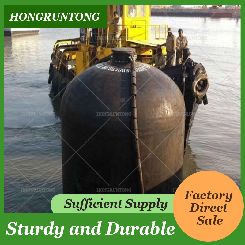
Submarine Fenders are specialized marine protection systems developed to manage contact loads between submarine hulls and berthing structures during docking, mooring, positioning, and selected maintenance operations. Their design must account for underwater hull geometry, restricted installation space, changes in water level, and the need to avoid excessive pressure on sensitive external surfaces. Compared with conventional surface-vessel fender arrangements, submarine fender systems require particular attention to working depth, contact alignment, attachment stability, and the relationship between energy absorption and reaction force.
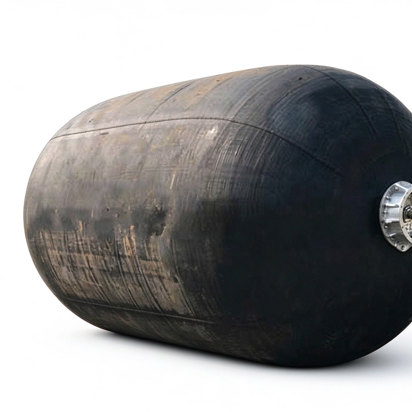
Hongruntong Marine provides Submarine Fender solutions that can be evaluated according to the vessel's dimensions, berthing arrangement, operating environment, and maintenance requirements. Depending on the project, the system may incorporate a reinforced rubber body, a hydro-pneumatic configuration, ballast components, pressure-control valves, chains, shackles, and supporting hardware. The final construction should be selected according to the actual operating conditions rather than relying on a standard configuration without engineering review.
Structural Materials and Construction
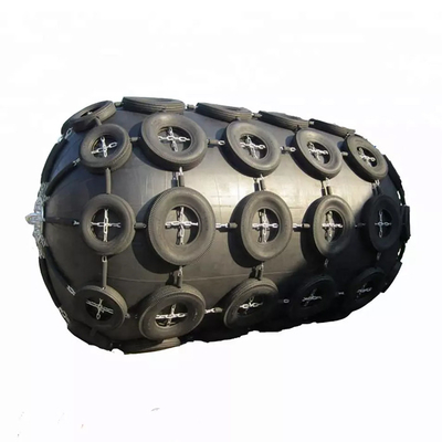
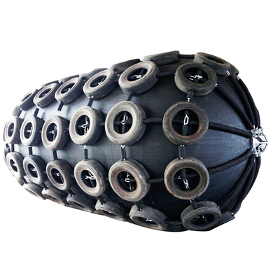
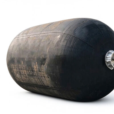
The rubber body can be manufactured from a marine-grade elastomer reinforced with multiple layers of synthetic tire-cord fabric. The elastomer provides flexibility and a protective contact surface, while the reinforcement helps control expansion and withstand tensile loading under the specified operating conditions. The external cover must be suitable for seawater exposure, abrasion, ultraviolet radiation, and temperature variation within the intended service environment.
For hydro-pneumatic configurations, the pressure-retaining structure, valves, seals, and end connections must be compatible with the specified internal pressure. The reinforcement architecture and bonding process are important because local construction defects may affect dimensional stability and long-term performance. End fittings and restraint hardware must also be designed to transfer the expected loads without creating unsuitable stress concentrations.
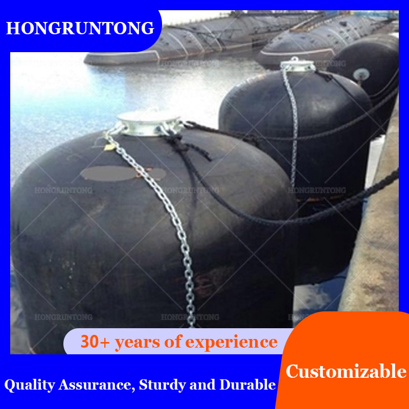
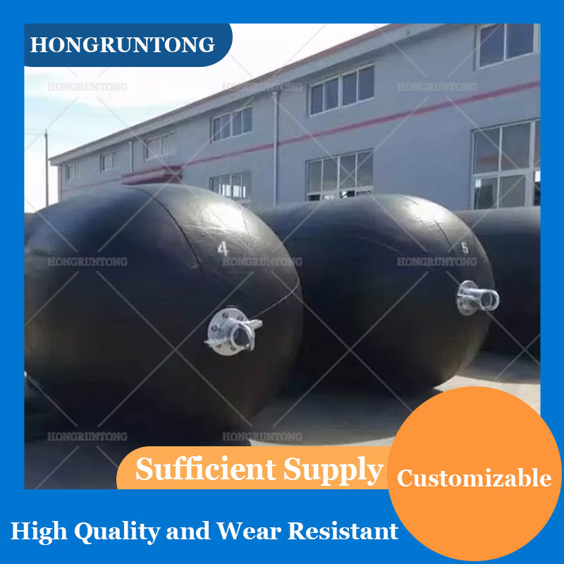
The selection of chains, shackles, metallic fittings, and protective coatings should account for working loads, corrosion exposure, material compatibility, and maintenance accessibility. The entire assembly should be treated as one protective system, with the rubber body, pressure-control components, and attachment hardware designed to work together.
Installation Adaptability and Working Position
Submarine berthing arrangements differ in quay height, water depth, tidal range, available mounting space, and vessel geometry. A suitable fender system must maintain the intended contact region throughout the specified operating conditions while avoiding interference with external appendages and sensitive hull areas.
For hydro-pneumatic fenders, the working position is influenced by internal pressure, water-filling ratio, ballast weight, and attachment geometry. These parameters should be established during design and verified during commissioning. The supporting frame or backing arrangement must accommodate the required loads, while the restraint system should limit unwanted movement without restricting the fender's intended deformation.
Fender spacing and installation height should be determined from the vessel's underwater hull profile and the berth configuration. If the vessel or operating water levels change, the suitability of the existing arrangement should be reassessed before adjustments are made.
Performance and Operational Reliability
The primary performance objective is to absorb the specified berthing energy while maintaining reaction forces and contact pressures within acceptable limits. These requirements depend on the vessel's effective berthing mass, approach velocity, berthing angle, available deformation space, and the structural characteristics of the supporting berth.
Energy absorption alone is not sufficient to establish suitability. The fender must also provide an appropriate load response and effective contact area for the particular hull geometry. Where sensitive coatings or external components are present, contact pressure and positioning require additional consideration.
A properly configured system can support more consistent berthing procedures and simplify inspection and maintenance planning. Its actual performance depends on correct product selection, installation, operating settings, and compliance with the approved technical specification.
Dimensions, Inspection and Service Planning
Submarine Fenders can be specified in different diameters, lengths, working drafts, and attachment arrangements. Selection should consider the vessel's principal dimensions, berth geometry, operating water levels, allowable reaction force, required energy absorption, and installation constraints. For hydro-pneumatic products, the technical specification should also identify pressure limits, water-filling requirements, ballast configuration, and valve arrangements.
Before installation, the purchaser should verify product dimensions, connection details, material documentation, and applicable inspection records. After commissioning, inspection should cover the rubber body, pressure-control components, restraints, hardware, and supporting structure. A documented maintenance program helps identify deterioration and abnormal movement before these conditions compromise the protective arrangement.
Case Study: Berthing Protection Upgrade for a Submarine Support Facility in a Tidal Harbor
A representative engineering scenario concerns a submarine support facility operating in a tidal harbor. The facility regularly accommodates a diesel-electric submarine with an approximate submerged displacement of 2,500 tonnes. The vessel uses a fixed quay for routine alongside operations, scheduled inspections, and technical servicing.
The existing fender arrangement had been installed for an earlier operating configuration. Following changes in berthing procedures, the facility identified difficulties maintaining a consistent underwater contact position during different water levels. Inspection personnel also reported that some connection points were difficult to access, making routine checks more time-consuming than expected. The facility therefore required a revised arrangement that would improve positioning control and simplify maintenance.
The engineering review began with an assessment of the submarine's principal dimensions, maximum beam, underwater hull profile, and the locations of vulnerable external components. The quay drawings were reviewed to determine the available mounting space, the condition of the supporting structure, and the anticipated load-transfer path. The tidal range, expected relative movement, and normal berthing conditions were included in the design assessment.
A revised Submarine Fender arrangement was then evaluated. The selected configuration would be required to maintain the intended contact region while providing suitable energy absorption and an acceptable reaction force. If a hydro-pneumatic system were used, the engineering specification would define the internal pressure, water-filling ratio, ballast weight, and working draft. The proposed fender spacing would be checked against the hull geometry to reduce the risk of interference with sensitive components.
The attachment system would be reviewed to ensure that chains, shackles, fittings, and supporting interfaces were suitable for the anticipated service loads. Maintenance accessibility would be incorporated into the layout, allowing personnel to inspect pressure-control components and connection points without unnecessary dismantling. The design would also establish clear inspection points and a documented procedure for checking the fender's working position.
Before installation, the project team would verify the approved drawings, dimensions, materials, and specified factory inspection records. During commissioning, personnel would check attachment security, working draft, pressure settings where applicable, and clearance from the vessel and surrounding structures. Initial berthing operations would be monitored under controlled conditions to verify that the contact arrangement performed as intended.
The expected outcome would be a more repeatable berthing arrangement, easier access for routine inspection, and clearer maintenance responsibilities. Inspection records could be used to track wear, corrosion, pressure variation, and movement over time. These records would also support future decisions about repair, adjustment, and replacement.
The approach can be adapted to other tidal-harbor facilities by using verified vessel data and site-specific measurements. Any improvement in inspection time, operational efficiency, or maintenance expenditure would need to be demonstrated through actual site records. This is an illustrative engineering scenario rather than a claim of a verified Hongruntong Marine customer project.

Specifications
| Product Name |
Submarine Fenders |
| Material |
SBR, NR |
| Size Available |
3.3*10.6M |
| Tensile Strength |
=> 18 MPA |
| Density |
90+/-5 |
| Colour |
Black |
| Application |
Submarine, ferry, oil rigs and so on |
| Hardness |
40-70 Shore A |
| Elongation |
=> 400 |
| Tear Strength |
=> 400 N/cm |
| Breaking Strength |
>310 |
|
Chemical Resistance
|
Fuel A: No deterioration |
| Oil 3: No deterioration |
| Lubricating oil: No deterioration |
| Cutting oil: No deterioration |
| Dilute HCL: No deterioration |
Diameter x
Length |
Initial
Internal
Pressure |
Ship
Radius |
Water
Ratio |
Guaranteed
Energy
Absorption |
Reaction
Force
at GEA |
Hull
Pressure
at GEA |
Deflection
at GEA |
| (mm x mm) |
(kPa) |
(mm) |
(%) |
(kJ) |
(kN) |
(kPa) |
(%) |
| 1500 x 6100 |
50 |
3000 |
60% |
131 |
562 |
140 |
51% |
| 80 |
186 |
754 |
188 |
| 1700 x 7200 |
50 |
4000 |
65% |
167 |
682 |
137 |
47% |
| 80 |
239 |
918 |
184 |
| 2000 x 6000 |
50 |
4000 |
70% |
135 |
544 |
131 |
41% |
| 80 |
194 |
736 |
177 |
| 2500 x 5500 |
50 |
4500 |
65% |
225 |
769 |
135 |
41% |
| 80 |
322 |
1035 |
182 |
| 2500 x 7700 |
50 |
4500 |
70% |
326 |
1016 |
136 |
41% |
| 80 |
470 |
1368 |
183 |
| 3300 x 6500 |
50 |
4500 |
75% |
307 |
887 |
127 |
35% |
| 80 |
442 |
1203 |
173 |
| 3300 x 10600 |
50 |
5000 |
65% |
1003 |
2137 |
142 |
47% |
| 80 |
1429 |
2863 |
190 |
| 4500 x 9000 |
50 |
5000 |
60% |
1439 |
2401 |
138 |
46% |
| 80 |
2059 |
3228 |
185 |
| 4500 x 12000 |
50 |
6000 |
65% |
1977 |
3198 |
141 |
46% |
| 80 |
2819 |
4277 |
189 |
Characteristics
Flexible Configuration for Different Berth Geometries
Submarine Fender installations vary considerably according to quay height, water depth, vessel dimensions, tidal range, and available mounting space. A configuration designed for one facility may not provide the correct contact position or deformation characteristics at another. Flexible configuration is therefore an important design consideration when selecting a fender for a dedicated submarine berth or maintenance facility.
The design process should begin with verified vessel dimensions and a review of the underwater hull profile. Maximum beam, hull curvature, external appendages, and the intended contact region help determine the required fender dimensions and installation positions. Berth drawings provide information about the available support points, structural clearances, and practical restrictions affecting installation.
For hydro-pneumatic systems, the internal pressure, water-filling ratio, ballast weight, and restraint geometry influence the working draft and orientation. These variables must be coordinated to maintain the intended contact position throughout the specified water-level range. The arrangement should also be checked for interference with adjacent structures and for sufficient access to inspection points.
Customized dimensions may include fender diameter, effective length, connection spacing, end fittings, and supporting hardware. Any customization affecting structural strength, pressure retention, or performance characteristics must be reviewed against the approved engineering specification. The design should identify the operating conditions for which the configuration is intended and the limits beyond which reassessment is required.
This approach is particularly useful for retrofit projects, where the existing berth structure may restrict the dimensions and mounting positions available. A site survey and review of the current arrangement can help identify practical installation constraints before manufacturing begins. By considering the complete installation rather than the fender body alone, the project team can develop a configuration that better fits the vessel, berth, and maintenance requirements.
Stable Positioning and Controlled Underwater Contact
Maintaining the correct working position is essential for submarine fender performance. If a fender moves vertically, rotates excessively, or drifts away from its intended location, the contact region may no longer align with the vessel's hull. Such movement can reduce protection effectiveness and create unwanted interaction with sensitive external components.
Hydro-pneumatic fenders use a combination of internal air pressure, partial water filling, and ballast to establish the required floating position. The resulting working draft depends on the combined effects of buoyancy, weight distribution, dimensions, and attachment geometry. These parameters should be established during engineering design and confirmed during commissioning.
The restraint arrangement must maintain alignment while accommodating the fender's intended movement and deformation. Chains, shackles, and supporting interfaces should be specified for the anticipated loads and environmental exposure. Excessive restraint may interfere with the intended response, while inadequate restraint may allow unwanted displacement. The approved design must therefore define both the connection arrangement and its permissible movement.
The contact position should be checked against the underwater hull profile, including the locations of hydroplanes and other appendages. Where the submarine has specialized coatings or acoustic tiles, the allowable contact conditions should be confirmed with the relevant vessel authority. The system should not rely on uncontrolled movement to find a suitable contact point.
During commissioning, personnel should verify the fender's working draft, orientation, connection security, and clearance from adjacent structures. Operating instructions should identify the approved pressure and filling settings, along with the conditions that require inspection or adjustment. Consistent positioning helps the facility maintain a predictable berthing arrangement and provides a clearer basis for routine maintenance.
Durability Under Repeated Contact and Marine Exposure
A Submarine Fender must withstand repeated contact loading while remaining exposed to seawater and other environmental influences. Its durability depends on the rubber compound, reinforcement architecture, bonding integrity, end construction, and quality of the attachment hardware. These elements must be selected and manufactured as a coordinated system.
The rubber cover provides flexibility and resistance to surface wear, while synthetic tire-cord reinforcement helps maintain structural stability under the specified loading and pressure conditions. The reinforcement layout should be appropriate for the intended deformation and internal pressure. Rubber preparation, reinforcement placement, curing, and bonding require consistent manufacturing controls to reduce the risk of premature deterioration.
Environmental exposure must also be considered. Seawater, ultraviolet radiation, temperature changes, and abrasive contact may affect the external surface over time. Metallic components can experience corrosion, particularly at connection interfaces and areas where protective coatings have been damaged. Material selection and maintenance planning should address the specific conditions at the installation site.
Inspection procedures should cover cuts, cracks, unusual bulging, exposed reinforcement, damaged fittings, corrosion, and signs of leakage where applicable. The operator should record significant changes and compare them with the product's specified limits. Any repair must follow an approved procedure suitable for the material and operating conditions.
Durability should not be represented by an unsupported fixed service life. The actual maintenance interval and replacement decision depend on operating intensity, berthing conditions, environmental exposure, and inspection results. A defined maintenance program allows the facility to identify deterioration and take corrective action before it affects the intended protective function.
Integrated Hardware and Maintenance Accessibility
The fender body, attachment hardware, valves, ballast components, and supporting structure jointly determine the effectiveness of the complete system. Even when the rubber body meets its specified performance requirements, unsuitable connections or poor access for inspection can create operational problems. An integrated design should therefore address load transfer, corrosion protection, installation procedures, and routine servicing.
Chains, shackles, and end fittings should be selected according to the expected working loads and connection geometry. Their material and protective treatment must be suitable for the environment, and the design should account for potential wear at moving interfaces. Where different metals are used together, material compatibility should be reviewed to manage the risk of galvanic corrosion.
Installation drawings should define attachment positions, lifting arrangements, fender spacing, and restraint geometry. The supporting structure must be checked for the loads transferred through the assembly. Installation personnel should also have clear instructions for handling the product and verifying the connection arrangement before commissioning.
Maintenance accessibility should be planned before the fender is installed. Pressure valves, connection points, and inspection areas should be accessible for routine checks. This can reduce the need for unnecessary removal of adjacent components and make it easier to identify deterioration or abnormal operating conditions.
The maintenance plan should specify the inspection items, recording procedures, and criteria for reporting defects. For hydro-pneumatic configurations, pressure readings and working draft should be checked in accordance with the approved operating instructions. Damaged hardware, leakage, abnormal movement, or deterioration that may affect safe operation should be assessed promptly.
An integrated hardware and maintenance approach helps the operator manage the fender as a complete marine protection system rather than as an isolated rubber component. It also supports more consistent inspection, repair planning, and future replacement decisions.
Applications
Tidal-Harbor Submarine Berths
Submarine berths located in tidal harbors must accommodate changes in water level while maintaining an appropriate underwater contact position. Submarine Fenders can be configured according to the vessel's hull geometry, quay layout, operating water depth, and required contact region. For hydro-pneumatic systems, working draft and ballast arrangement should be selected to suit the specified tidal range.
The design must consider the expected vessel movement, berth structure, allowable reaction force, and contact pressure requirements. Fender spacing and attachment geometry should be verified against the submarine's underwater profile. Routine checks of position, pressure, connections, and rubber condition help maintain consistent performance as operating conditions change.
Submarine Maintenance and Retrofit Projects
Shipyards and maintenance facilities may require replacement or upgraded fender systems when vessel configurations, berth arrangements, or operating procedures change. A retrofit assessment should review existing mounting points, available space, hull clearance, and the condition of the supporting structure. The objective is to ensure that the proposed configuration meets current requirements rather than simply reproducing the original dimensions.
Fender placement should preserve access to the maintenance areas and avoid interference with external appendages. Where hydro-pneumatic fenders are used, pressure settings, water-filling ratio, ballast configuration, and working draft should be documented. Commissioning and inspection procedures should also be established to verify the installation before normal operation.
Specialized Marine Support Structures
Submarine Fenders may be evaluated for selected marine support structures where controlled contact protection is required below the waterline. Applications may include specialized vessel support facilities and marine installations with defined contact geometry. Suitability depends on the operating loads, water depth, environmental conditions, and structural arrangement.
For exposed locations, the engineering assessment should consider current, wind, wave-induced movement, attachment loads, and inspection access. The support structure must be capable of accommodating the forces transmitted through the fender system. Product suitability should be confirmed against the actual operating envelope and project specification.
Why Choose Hongruntong Marine
More Than 30 Years of Manufacturing Experience
Hongruntong Marine has more than 30 years of manufacturing experience. For specialized marine fender projects, manufacturing experience supports the coordination of product construction, material selection, dimensional requirements, and quality-control procedures. These considerations are particularly important when a fender must be configured for a specific vessel and installation environment.
Reinforced rubber products require consistent control over material preparation, reinforcement placement, bonding, forming or molding, and final inspection. Variations in these processes can affect dimensions, structural integrity, and deformation behavior. A defined production and inspection plan helps ensure that the supplied product corresponds to the approved specification.
For hydro-pneumatic configurations, manufacturing requirements also include pressure-retaining components, valves, seals, end fittings, and associated connections. These components must be compatible with the specified pressure and operating conditions. Where required, pressure testing and dimensional verification should be carried out according to agreed procedures and acceptance criteria.
Hongruntong Marine can coordinate the customer's technical requirements with the manufacturing and documentation arrangements agreed for the order. This may include product drawings, material records, inspection reports, accessory specifications, and packaging requirements. The exact scope should be confirmed before production so that both parties understand the required deliverables.
Manufacturing experience should be supported by objective inspection and test evidence. By defining technical requirements and acceptance criteria in advance, the purchaser can establish a clearer basis for evaluating product conformity and planning installation.
Customized Product Dimensions and Installation Arrangements
Submarine berths differ in geometry, water depth, tidal range, structural support, and maintenance requirements. A fender configuration suitable for one facility may not provide the correct working position or performance at another. Hongruntong Marine can discuss customized dimensions and installation arrangements according to the project requirements and available manufacturing options.
The engineering review should consider vessel dimensions, maximum beam, underwater hull profile, contact location, and external appendages. The berth drawings should establish the available installation space, support points, and structural clearances. Expected berthing conditions and permissible contact loads should also be defined before selecting the final configuration.
For hydro-pneumatic products, customization may involve the body dimensions, pressure settings, water-filling ratio, ballast weight, working draft, and restraint hardware. These parameters must be coordinated because a change in one variable may influence the fender's orientation or reaction characteristics. Any change affecting structural integrity or pressure retention should be reviewed against the approved design.
For replacement projects, existing equipment dimensions and inspection records can provide useful reference information. However, the original configuration should be reassessed if the vessel, berth structure, or operating requirements have changed. A site survey or updated drawing review can help identify potential interference and installation constraints before production.
Customized configuration provides a practical way to address the actual installation rather than relying on a generic product description. The final arrangement should be documented through approved drawings and a technical specification that identifies the intended operating conditions and acceptance criteria.
Material Selection and Manufacturing Quality Control
Material selection directly influences fender flexibility, structural strength, resistance to environmental exposure, and maintenance requirements. The rubber compound, reinforcement fabric, end fittings, valves, and metallic accessories must be selected according to the product design and the conditions expected during service.
Hongruntong Marine can coordinate the agreed material and quality requirements before production. These requirements may include the rubber specification, reinforcement construction, dimensional tolerances, accessory materials, corrosion protection, and applicable inspection procedures. A clear specification helps avoid ambiguity concerning the supplied product and its intended operating limits.
Manufacturing quality control should address the stages that have the greatest effect on performance. Depending on the design, these may include material preparation, reinforcement placement, bonding, forming or molding, fitting installation, and final dimensional inspection. Pressure-retaining products may require additional checks of valves, seals, end connections, and pressure integrity.
The purchaser should define the required inspection and testing scope in advance. Possible requirements include dimensional inspection, material documentation, pressure testing, performance verification, and independent inspection where contractually specified. Acceptance criteria should identify the applicable test method and the conditions under which results will be evaluated.
Certification requirements also need to be confirmed against the actual product type. A general statement about marine fender manufacturing does not establish compliance with a particular international standard. Clear documentation and agreed acceptance procedures allow the customer to verify the supplied product against the requirements of the project.
Technical Coordination and Maintenance Support
The successful use of a Submarine Fender depends on more than manufacturing quality. Installation, commissioning, operation, and maintenance must all follow the approved configuration. Hongruntong Marine can coordinate technical information within the agreed supply scope to help the customer understand the product dimensions, attachment requirements, operating limits, and inspection procedures.
Before installation, the project team should confirm the approved drawings, handling instructions, connection hardware, and required clearances. For hydro-pneumatic systems, the operating information should identify pressure limits, water-filling requirements, ballast configuration, and the checks needed to establish the intended working draft.
Commissioning should verify the fender position, attachment security, and clearance from surrounding structures. Personnel should also confirm that the installed arrangement corresponds to the approved drawings and that any pressure or filling settings remain within the specified limits. Initial operating checks should be conducted under controlled conditions appropriate to the installation.
Routine maintenance should include inspection of the rubber body, valves, fittings, restraints, and supporting structure. Abnormal deformation, leakage, corrosion, damaged connections, or unexpected movement should be investigated. Repair or adjustment should follow the manufacturer's instructions and the applicable site procedures.
Inspection records provide a practical basis for maintenance scheduling and replacement planning. They can help the facility identify recurring problems and compare the condition of equipment over time. Clear technical coordination supports more consistent maintenance decisions, although actual service life and operating costs remain dependent on the specific installation and service conditions.
FAQ
1. Can Submarine Fenders accommodate tidal changes?
Hydro-pneumatic Submarine Fenders can be configured for a defined operating water-level range by considering the working draft, internal pressure, water-filling ratio, ballast weight, and attachment arrangement. The required configuration must be established from the vessel's underwater hull profile and the berth geometry. Actual suitability should be verified against the specified tidal range and operating conditions.
2. What information is needed for a retrofit project?
Useful information includes the existing fender dimensions, mounting positions, berth drawings, water depth, tidal range, submarine dimensions, underwater hull profile, and locations of sensitive external components. The customer should also provide any known performance requirements, including allowable reaction force and contact pressure. A site survey may be necessary when the existing installation drawings are incomplete or the support structure has changed.
3. How can the fender remain correctly positioned during operation?
Positioning depends on the design geometry, restraint arrangement, ballast configuration, and, for hydro-pneumatic products, internal pressure and water-filling ratio. Chains, shackles, and supporting hardware should be specified for the anticipated loads. During commissioning, the working draft, orientation, attachment security, and clearance from surrounding structures should be checked. Operating adjustments should follow approved instructions.
4. What should be included in a Submarine Fender inspection plan?
The inspection plan should cover rubber deterioration, cuts, cracks, exposed reinforcement, abnormal deformation, pressure variation, leakage, damaged fittings, corrosion, and restraint condition. It should also identify inspection frequency, recording requirements, defect-reporting procedures, and criteria for repair or removal from service. The plan should follow the manufacturer's recommendations and account for the actual operating environment.
5. Which performance and quality documents should be requested before purchase?
The purchaser should identify the required dimensions, material specifications, energy absorption, reaction force, allowable contact pressure where applicable, pressure limits, and installation details. Supporting documents may include material records, dimensional inspection reports, applicable pressure-test results, performance-test reports, and certificates of conformity. Any required third-party inspection or compliance with a named standard should be agreed before production, with applicability confirmed for the exact product configuration.


 Your message must be between 20-3,000 characters!