Product Overview
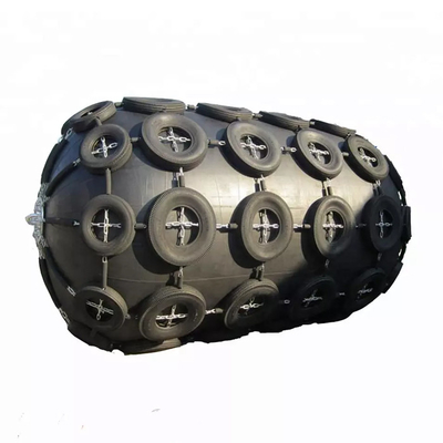
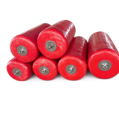
The Floating Foam Fender is a marine impact-protection system designed to absorb berthing energy, distribute contact loads, and reduce the risk of damage to vessels, floating platforms, offshore facilities, and port infrastructure. It is used in marine environments where vessels operate alongside fixed or floating structures and where the protection system must accommodate changes in water level, relative vessel movement, and repeated contact.
The fender generally comprises a closed-cell foam core, a protective outer elastomeric covering, and connection components configured according to the intended installation. The core provides buoyancy and compression-based energy absorption, while the outer covering protects the internal structure from abrasion, tearing, and environmental exposure. Material composition, reinforcement design, and connection details should be specified according to the operating conditions and the performance requirements of the project.
Working Principle
The working principle of a Floating Foam Fender relies on the deformation of the foam core under an applied load. When a vessel approaches a berth or makes contact with another vessel, the fender compresses and absorbs part of the kinetic energy generated by the relative movement. The resulting reaction force is transmitted through the contact interface and attachment system to the supporting structure.
The relationship between absorbed energy, compression, and reaction force depends on the foam characteristics, fender dimensions, loading rate, and deformation range. A suitable design must therefore balance energy absorption with allowable reaction force and available clearance. If the fender is undersized, it may not provide adequate protection under the specified operating conditions; if its deformation is excessive, it may allow unwanted contact between the protected surfaces.
The buoyant construction enables the fender to remain at the water surface and respond to variations in water level. This characteristic is particularly relevant in tidal ports, floating terminals, ship-to-ship transfer locations, and offshore service areas where the contact elevation changes during operation. The closed-cell foam structure limits water absorption and supports flotation without requiring an internal pressurized chamber. Unlike pneumatic fenders, foam-filled designs do not depend on maintaining a specified internal air pressure for their basic operating form. Nevertheless, buoyancy, compression performance, and long-term durability remain dependent on the quality of the foam, the integrity of the external skin, and the suitability of the finished assembly for the service environment.
Construction & Outer Covering
The outer covering is an important component of the overall structure because it protects the foam core from direct mechanical contact. Depending on the design specification, the covering may use polyurethane elastomer or another marine-suitable protective material. Reinforcement may be incorporated to improve resistance to tearing and localized stress, especially where the fender experiences repeated contact or handling.
The skin and core must remain compatible throughout the expected deformation range. Inadequate bonding, unsuitable material selection, or poorly designed end connections may reduce service reliability even when the nominal dimensions are appropriate. For this reason, product assessment should consider the complete assembly rather than evaluating the foam core or outer covering in isolation.
Configuration & Selection
Floating Foam Fenders can be configured for different vessel sizes, contact geometries, installation clearances, and attachment arrangements. The selection process should consider vessel displacement, approach velocity, berthing angle, wave conditions, tidal variation, supporting-structure strength, and the expected frequency of contact.
For offshore and ship-to-ship applications, relative vessel motion and uneven hull geometry may create nonuniform loading across the fender surface. The layout should therefore be assessed to ensure that the contact area, deformation allowance, and attachment system are compatible with the expected load direction. Installation planning must also account for lifting access, mooring arrangements, and the possibility of the fender becoming trapped against structural projections.
The principal engineering benefit of the Floating Foam Fender is its combination of flotation, impact-energy absorption, and a pressure-independent core. This configuration can reduce dependence on inflation equipment and routine pressure adjustment while providing a compliant contact interface for marine operations. The fender may serve as primary or supplementary protection, depending on the project design and risk assessment. Appropriate maintenance includes inspection of the outer skin, connections, lifting points, and supporting structure, together with checks for abnormal deformation or changes in flotation.
Case Study: Foam Fender Integration at a Tidal Commercial Port
A representative port-improvement project involved a commercial harbor handling general cargo vessels, coastal freighters, and marine service craft. The berth experienced substantial variation in water level during the tidal cycle, and the vessel contact position changed as ships arrived, secured alongside, and departed. The existing protection arrangement was not consistently aligned with the principal contact zones across the full operating range. This created a need for a floating protection system that could follow water-level changes while maintaining a suitable contact interface between the vessels and the berth.
The project team reviewed the berth geometry, vessel operating profile, expected approach conditions, and the location of the existing structural contact points. Particular attention was given to the different hull forms using the berth, because the contact area of a coastal freighter could differ considerably from that of a smaller service vessel. The assessment also considered the available installation space, mooring-line clearances, access to the quay, and the structural capacity of the proposed attachment points. These parameters established the basis for selecting fender dimensions and determining the required operating position.
A Floating Foam Fender arrangement was proposed to provide buoyant protection along the designated contact areas. The closed-cell foam core offered flotation and deformation under load, while the external protective skin was selected to withstand routine surface contact and handling. The connection system was planned to retain the fender in the intended position while allowing appropriate movement as water levels changed. Before installation, the project team needed to verify the required energy-absorption performance, reaction-force limits, allowable compression, and compatibility between the connection hardware and the berth structure.
The installation process included positioning the fenders at the identified contact zones, inspecting the supporting attachment points, and confirming that the fenders could move without interfering with vessel access or quay operations. The team also reviewed the approach and berthing procedures to reduce the likelihood of excessive impact loads. Since fender performance depends on the conditions under which contact occurs, operational controls remained an important part of the protection arrangement. The equipment was not treated as a substitute for suitable vessel handling, mooring procedures, or berth operating limits.
In this illustrative scenario, the expected benefit was a more adaptable protection system across changing tidal conditions. The floating configuration could help maintain contact protection at different water levels, while the foam core provided energy absorption without dependence on internal air pressure. Ongoing inspection would be used to monitor outer-skin wear, connection integrity, deformation, and flotation. Any measurable improvement in damage prevention, maintenance demand, or berth availability would need to be established through actual operating records. The case demonstrates the importance of matching fender configuration to berth geometry, tidal conditions, and the operating characteristics of the vessels using the facility.
Specifications
| Product Name |
Floating Foam Fender |
| Product Type |
Closed-Cell Foam Filled Floating Fender |
| Core Material |
High-Density Closed-Cell Polyethylene Foam |
| Outer Skin |
Reinforced Polyurethane or Elastomeric Rubber |
| Buoyancy |
Unsinkable, Positive Buoyancy |
| Energy Absorption |
High Energy Absorption With Low Reaction Force |
| Weather Resistance |
UV, Seawater, And Aging Resistant |
| Installation |
Chain or Bracket Mounting, Customizable |
| Service Life |
15–20 Years Under Normal Operating Conditions |
Performance Data (60% Compression)
| Diameter × Length (mm) |
Energy Absorption (kNm) |
Reaction Force (kN) |
Approx. Weight (kg) |
| 300 × 1000 |
3.8 |
54 |
11 |
| 500 × 1000 |
10.6 |
91 |
41 |
| 600 × 1000 |
15.3 |
109 |
49 |
| 600 × 1000 |
18.3 |
131 |
55 |
| 700 × 1500 |
31 |
191 |
85 |
| 750 × 1500 |
36 |
204 |
89 |
| 900 × 1800 |
62 |
294 |
140 |
| 1000 × 1500 |
64 |
272 |
125 |
| 1000 × 2000 |
85 |
363 |
170 |
| 1200 × 2000 |
122 |
436 |
275 |
| 1200 × 2400 |
146 |
523 |
365 |
| 1250 × 2000 |
132 |
454 |
353 |
| 1250 × 2500 |
165 |
567 |
410 |
| 1500 × 3000 |
286 |
817 |
570 |
| 1500 × 4000 |
381 |
1089 |
720 |
| 1700 × 3000 |
367 |
926 |
700 |
| 1700 × 3500 |
428 |
1080 |
780 |
| 1800 × 3000 |
412 |
980 |
850 |
| 1800 × 3600 |
494 |
1176 |
965 |
| 2000 × 3000 |
508 |
1089 |
965 |
| 2000 × 3500 |
593 |
1271 |
1100 |
| 2000 × 4000 |
678 |
1452 |
1220 |
| 2400 × 4000 |
976 |
1743 |
1720 |
| 2400 × 4800 |
1171 |
2091 |
2140 |
| 2500 × 4000 |
1059 |
1815 |
1865 |
| 2500 × 5000 |
1324 |
2269 |
2500 |
| 2500 × 5500 |
1456 |
2496 |
2675 |
| 2700 × 5400 |
1668 |
2647 |
2865 |
| 3000 × 5000 |
1925 |
2750 |
3200 |
| 3000 × 6000 |
2287 |
3268 |
3740 |
| 3300 × 6500 |
2998 |
3894 |
4735 |
| 3600 × 7200 |
3953 |
4706 |
5800 |
| 4000 × 8000 |
4522 |
5809 |
8700 |
| 4200 × 8400 |
6277 |
6405 |
10000 |
| 4500 × 9000 |
7720 |
7353 |
10700 |
Key Features
Controlled Compression and Energy-Absorption Characteristics
A Floating Foam Fender is designed to absorb impact energy through compression of its internal foam core. When a vessel makes contact, the foam deforms under load, creating a compliant interface between the vessel and the protected structure. The resulting performance is determined by the material's compression behavior, foam density, fender dimensions, and the amount of deformation permitted by the installation. These factors influence both the energy absorbed and the reaction force transferred to the supporting structure. Engineering selection must therefore evaluate the complete force-deformation relationship rather than relying only on the fender's external dimensions.
The required energy-absorption capacity should be established from the anticipated vessel displacement, approach velocity, berthing angle, and other relevant operating parameters. Where multiple vessel types use the same berth, the design should account for the range of expected operating conditions and identify the governing load case. The fender must also retain sufficient clearance to prevent direct contact after compression. A suitable design provides a controlled deformation range that supports the intended protection function without imposing unacceptable loads on the vessel hull, supporting structure, or connection system.
Buoyant Performance Under Changing Water Levels
The foam-filled structure allows the fender to float without relying on an inflatable air chamber. This makes the configuration suitable for locations where the contact elevation changes because of tides, vessel draft, or movement of floating facilities. Closed-cell foam limits water absorption within the core and helps maintain buoyancy during service. The actual flotation capacity, however, depends on the material properties, the total assembly weight, the fender dimensions, and any additional equipment attached to the unit.
For tidal ports and floating terminals, buoyancy must be considered together with fender positioning and restraint. The connection system should prevent unwanted displacement while allowing the movement required by the installation. If the fender is restrained too tightly, water-level changes or vessel movement may create unnecessary loads in the connections. If it is insufficiently restrained, the fender may move away from the intended contact area. The installation design should therefore establish a suitable balance between positional control, movement allowance, and safe access for inspection.
Protective Outer Covering and Reinforced Construction
The outer covering is exposed to repeated contact, abrasion, environmental aging, and mechanical stress during handling. Its purpose is to protect the foam core and preserve the integrity of the fender assembly. Polyurethane elastomer and other suitable protective materials may be used according to the product design and the intended service environment. Reinforcement can improve resistance to tearing and localized stress, but its effectiveness depends on material selection, layer construction, bonding quality, and the way loads are transferred through the fender.
Inspection should focus on areas that experience concentrated loading, including end sections, attachment points, and repeatedly contacted surfaces. Cuts, cracking, exposed foam, or separation between the covering and core may indicate a need for further assessment. The suitability of the outer material should also be reviewed against ultraviolet exposure, seawater, temperature variation, and the expected contact surfaces. Selecting the protective covering for the actual operating environment helps reduce premature surface deterioration and supports more predictable maintenance planning.
Flexible Configuration for Different Marine Installations
Floating Foam Fenders can be specified in different diameters, lengths, and connection arrangements to suit project requirements. The external geometry affects the available contact area, deformation range, buoyancy, and energy-absorption capacity. Connection components must be compatible with the supporting structure and capable of handling the anticipated forces. Where lifting points or end fittings are required, their arrangement should be coordinated with the fender structure to avoid creating unnecessary stress concentrations.
Configuration design should begin with the installation conditions rather than a standard size assumption. Relevant inputs include vessel geometry, berthing approach, expected contact position, water-level variation, available clearance, maintenance access, and supporting-structure strength. For ship-to-ship operations, the design should consider the relative movement of both vessels and the possibility of uneven contact across the fender surface. Customized dimensions and connection details should be confirmed against documented technical requirements and verified before manufacture.
Applications
Tidal Commercial Ports and General Cargo Berths
Floating Foam Fenders can be used at commercial berths where vessels of different sizes operate under changing water levels. Their buoyancy helps maintain the contact interface as the tide rises or falls, while the foam core absorbs impact energy during controlled berthing. Suitable installations may include general cargo terminals, coastal shipping facilities, and service berths where the operating arrangement allows floating protection equipment to be installed safely.
The fender layout should be based on the berth geometry, expected vessel contact zones, and the required clearance during compression. The design should also consider the loads transmitted to the quay structure and the effect of the fender on mooring operations. Regular inspection of the outer covering and connections helps identify wear or damage before it affects the protection arrangement.
Shipyards and Vessel Maintenance Facilities
Shipyards frequently handle vessels with different hull shapes, dimensions, and maintenance requirements. Floating Foam Fenders can provide temporary or semi-permanent contact protection at suitable work berths, floating docks, and vessel service areas. Their foam-filled construction offers a compliant contact surface without requiring routine inflation, which may simplify equipment management in facilities where fenders are moved or repositioned for different work packages.
The application should be assessed for compatibility with the vessel's hull coating, the contact geometry, and the expected load direction. Particular care is required when fenders are used near protruding hull features, temporary scaffolding, or equipment installed during maintenance. The installation must not obstruct access or introduce additional hazards during lifting and repair operations. Inspection frequency should reflect the intensity of use and the likelihood of contact with tools, sharp edges, or construction materials.
Floating Terminals and Offshore Service Platforms
Floating Foam Fenders may be incorporated into protection arrangements for floating terminals, offshore service platforms, and other marine facilities where vessel contact occurs alongside a floating or semi-floating structure. The fender can move with changes in water level, while its foam core provides impact absorption during controlled vessel approach. This is useful where the relative position of the vessel and platform changes because of tide, draft, or environmental movement.
Engineering review should consider the motion of both structures, the expected contact area, wave conditions, and the loads imposed on the attachment system. The fender should be positioned so that it does not interfere with access routes, transfer equipment, or mooring lines. For offshore service, the outer material and connection hardware should be selected for the environmental exposure and inspected according to a defined maintenance schedule.
Why Choose Hongruntong Marine
Established Manufacturing Experience
Hongruntong Marine has more than 30 years of manufacturing experience, providing an industrial foundation for marine equipment production and project coordination. Floating Foam Fender manufacturing requires control over several interdependent elements, including foam characteristics, outer-covering materials, reinforcement, bonding, dimensions, and connection components. Variation in any of these elements can affect the finished product's flotation, compression behavior, resistance to surface damage, and suitability for the intended installation.
For B2B procurement, manufacturing experience is most useful when it supports clear technical communication and consistent production requirements. Buyers need to understand the proposed construction, the available performance information, and the inspection criteria that apply to their order. Hongruntong Marine can coordinate technical discussions around the project's intended use, operating conditions, and product configuration. Final acceptance should be based on confirmed specifications, documented inspection results, and the applicable requirements of the purchaser.
Engineering-Oriented Product Selection
Selecting a Floating Foam Fender requires more than matching a nominal diameter or length. The system must provide appropriate energy absorption while keeping reaction forces and deformation within the limits established for the installation. Vessel displacement, approach speed, berthing angle, contact geometry, tidal range, and supporting-structure capacity all influence the selection process. The required buoyancy and restraint arrangement must also be considered, particularly where the fender is expected to follow changing water levels.
Hongruntong Marine can review project information to help identify the technical parameters that need to be defined before an order is finalized. This may include installation drawings, vessel information, target performance, connection details, and the expected service environment. Where critical design inputs are missing, they should be clarified before the product configuration is confirmed. An engineering-oriented approach helps reduce the risk of selecting equipment that fits physically but does not meet the required protection performance.
Product Configuration and Manufacturing Coordination
Marine installations differ in contact geometry, available clearance, operating frequency, and attachment requirements. A suitable fender configuration should address these conditions through coordinated dimensions, material selection, and connection design. Hongruntong Marine can assess customization requirements within the available manufacturing scope, including specified dimensions, protective-covering options, and connection arrangements where technically feasible.
Customization should be documented in a clear product specification. This specification should identify the required dimensions, material construction, attachment details, inspection requirements, and any performance criteria that must be verified. Where a project includes special handling or installation constraints, these should be considered before production rather than addressed after delivery. Clear coordination among the purchaser, engineering team, and manufacturer helps align the finished equipment with the actual installation requirements.
Quality Inspection and Project Documentation
A Floating Foam Fender should be assessed as a complete assembly, not simply as a foam component with an external covering. Relevant quality checks may include dimensional inspection, visual examination of the outer skin, verification of connection components, and review of material specifications. Additional performance tests or third-party inspections can be included when required by the contract and confirmed in the inspection plan. The applicable methods and acceptance criteria should be agreed upon before production.
Hongruntong Marine can coordinate the technical documentation required for the confirmed order, subject to the agreed scope. Depending on the project, this may include product drawings, material information, inspection records, packing details, and maintenance guidance. Certification should be specified explicitly where required and confirmed for the actual product and production scope. Complete documentation supports incoming inspection, installation planning, asset management, and future maintenance decisions.
Frequently Asked Questions
1. How does a Floating Foam Fender absorb impact energy?
The fender absorbs impact energy through compression of its internal foam core. When a vessel makes contact, the foam deforms and provides a compliant interface that helps distribute the applied load. The energy-absorption capacity and reaction force depend on the foam characteristics, dimensions, loading conditions, and allowable deformation. Product performance should be verified against the project requirements.
2. Can Floating Foam Fenders be used in tidal ports?
Yes. Their buoyant construction allows them to accommodate changing water levels when the fender and attachment system are designed for the installation. The positioning, restraint arrangement, and movement allowance must be checked to ensure that the fender remains within the intended contact zone throughout the operating range.
3. Can the dimensions and connections be customized?
Dimensions and connection arrangements may be customized according to the project requirements and the manufacturer's available production capabilities. The specification should define the installation geometry, expected loads, material requirements, and attachment details. Any customized configuration should be confirmed through technical review before manufacture.
4. What should be checked before installation?
The installation team should verify the fender dimensions, material and product documentation, attachment compatibility, supporting-structure capacity, available clearance, and intended contact position. The team should also confirm that the fender can move as required without interfering with mooring lines, access routes, or adjacent equipment.
5. How can the service condition of a Floating Foam Fender be monitored?
Routine monitoring should include inspection of the outer skin, connection hardware, end sections, and attachment points. The operator should look for cuts, cracking, exposed foam, delamination, abnormal deformation, and changes in flotation. Inspection frequency should be adjusted to the operating environment and contact frequency, and any significant damage should be assessed before the fender returns to normal service.


 Your message must be between 20-3,000 characters!